Monday 12 September 2011

'Building the Beast' - My Tigger Models 1/32nd Scale Short Sunderland Mk1 build - Part 2

In the first post we left 'the beast' on the work bench having just been cut-out. Now, the work begins to make something of the two hull halves.........

Whilst I was sitting there just staring at the sheer bulk of 'the beast' my eye was drawn to the wing root stubs sticking out from each Port and Starboard hull half. I was pleased when I first saw the kit parts that the molding included for each wing root stub as it meant that a potential major joint had been eliminated and with it the chances of a crack appearing at a later date due to the stresses of the wing-to-hull join being right on the hull itself. Doing it this way meant that at least I had a decent chance to stick both wings on these stubs without having to resort to a huge amount of fairing-in of the wings to the hull at this juncture. The wing fairing would be a major job otherwise. However, that was not what I was looking at; what I noticed just sitting there was that the port wing root  fairing was sitting higher up the hull than the starboard!
"OMG" I thought....! That can't be right. But, unfortunately, it was. The fairing on the port side is a good two or three millimetre higher than the other and is only really noticeable from a head-on viewpoint. It is not noticeable at all from the side and I think that is due entirely to the sheer bulk (again) of the whole thing up close. Looking at a 1/72 scale kit part in-front of you is totally different than looking at this one.

Ok, so it's part of the mold and I will have to deal with it as the build goes on, I said to myself, whilst adding the point to the kit-build list that I had made up. I was already thinking of a way to sort the problem out. However, prospective customers and builders please note that it should be entirely practicable to achieve a solution for this without going to the lengths of major surgery. More on this subject later in the build.

However, having got over this problem, another one loomed up almost straight away! One of the things that any vac-form kit builder has to have in his portfolio is (1)  patience and (2) method aforethought.
The canopy transparency is a large fine molding and looks quite accurate
Patience because this isn't a 'shake n' bake' kit - a kit that is going to 'fall together' out of the box, indeed by its very nature no vac-form kit ever is, or will be. Every time I purchase and start a vac-form I go into a sort of 'building mode' that is best described as 'different to injection molded kit build'. I can't explain it any better than that; it's simply knowing that the kit in-hand is going to  bite you at some point and you have to determine when, to avoid it. That requires of the builder a large degree of patience as this kit is not going to be finished in a weekend, or indeed a number of weekends due entirely to the nature of the presentation of parts. That brings up the second state-of-mind; 'Method Aforethought' - the art of being able to think the build through from the start - then as you go along - always working out what to do next and after that, what to do again and again, concentrating on making sure that the kit will go together as you want, and the manufacturer intended.
Clearly marked here is the widest part of the canopy - this is what will govern the width of the hull
The vast majority of vac-form kits do not carry instructions of how to put them together or the order in which each of the parts should be added, totally different to more-or-less any commercially available injection molded kit, therefore apart from the fact that the parts have to be cut-out from a sheet of molded plastic card the builder is very much on his own and therefore that is why vac-forms are for experienced scale plastic model builders, not beginners.All of the past paragraphs then led me to another discovery on the hull of this kit; as supplied, it's moulded too wide for the cockpit canopy and the true dimensional measurements against the real Sunderland.
The canopy at this stage only fits where it touches
Well, actually that may not be entirely correct; 'Yes', it is too wide as molded but that may not be the fault of the kit manufacturer exactly. All vac-forms are made by forming heated sheet plastic over a mold. That mold can be either accurate or in-accurate; it won't matter to the plastic concerned as it will simply adopt the shape it is molded over and some manufacturers make certain allowances and this one has one of them. That is 'draw allowance', least-ways that is what I'm calling it.

It's not a serious problem in any way once you know about it, that is. And that is exactly where 'Method Aforethought' comes in. The cockpit canopy is a superb transparent molding contained within the kit and my 'inbuilt' vac-form experience reminded me that the canopy cannot be modified, it is a molding of a certain height and a certain WIDTH and that's that. It is, and will always be, 'as provided' for I doubt if there are many brave souls that would consider modifying it. This of course highlights another point that is particular to this, and other kits of the type and that is 'how accurate is the kit'? I mean, it stands to reason that the kit comes 'as molded', right? And the cockpit comes also as molded, so why don't they at least nearly match in width (?) I sat there thinking. The answer was the next job in-hand.
Here you can see the relative pencil markings showing the difference in fit
Realising that the cockpit canopy was not going to be modified, I was reluctant to start getting out the tape measure, calipers and set square and start pouring over the hull to see what the exact measurements are and then compare with the known dimensions of the Sunderland at various points across the width of the hull. Not that I'm one of the 'if it looks right, then it must be right' brigade you understand, it's just that with kit of this immense size, molded from a long-ago built wooden master that someone carefully crafted - slightly smaller than the required dimensions so that the width of the plastic card as molded would be taken into account in the finished molded piece - if you did go to all that trouble only to find that the hull is dimensionally 5mm too high or 5mm too wide, there is very little that one can do about it, and frankly dimensional errors of that magnitude wouldn't notice to the eye on a model of this sheer bulk.
Clearly here you can see the issue in relative width - not a fatal problem though
No, I wasn't going to go that route. It's fair enough to expect millimetre precision on today's state-of-the-art injection molded kits but this is different and it is far better to build it to it's common denominators than try to aim for scale precision. Mind you, I know of at least one person who has built this very kit complete with all the interior details! God knows how he did it..!
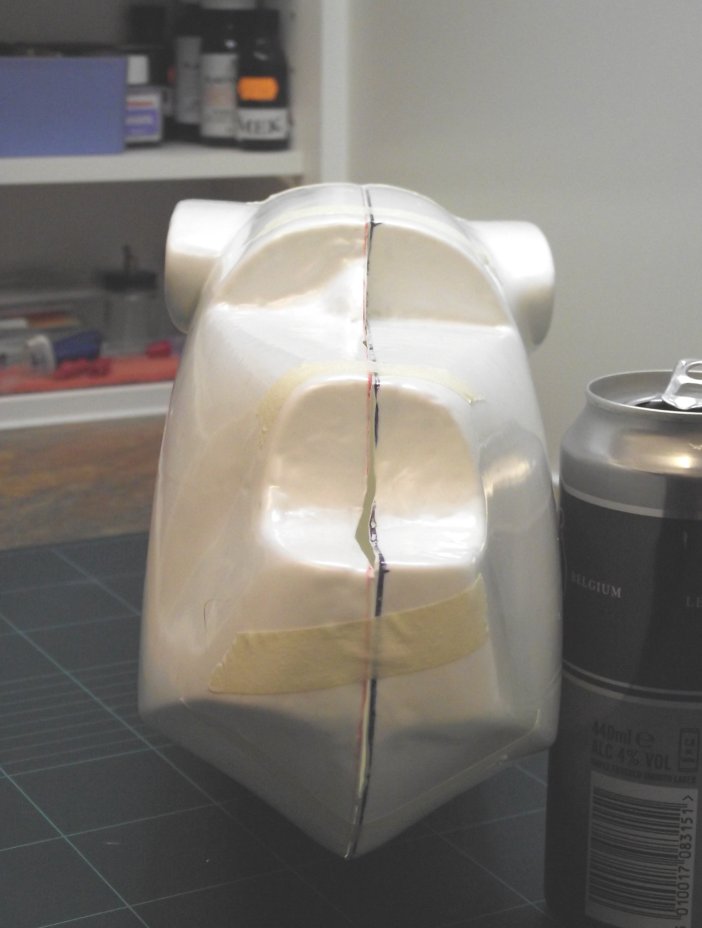
This is the amount - the black line - that has to be removed from each hull half, give or take a mm
So, enough of this rambling; I took the decision to take a closer look at the hull to see what could be done to narrow it. That's when I noticed that - I hadn't spotted it before - there is the faintest raised edging to both hull halves. It's so feint that you wouldn't spot it unless you really looked closely under strong overhead lighting, but it is there and I took measurements of it on both hulls. I compared that against the overall width of the canopy at it's rear end, the widest point and 'Bingo' it looked almost a perfect match! In fact, it was better than that, it was as good as it's going to get.

I followed this raised mark all around the hull with a roll of masking tape and for the photo's shown here - for clarity - I filled in the gap with a black fibre pen. The depth was at least 4mm on each hull half that had to be removed. Always cautious, I checked and double checked the measurements to ensure that I was not taking too much off (that would be a disaster) or too little (that is curable, but I didn't want to do the same job all over again).
Keep your fingers well away from the edge as you make these shallow cuts 
Once happy that all was as good as could be, with a heavy duty craft knife fitted with a brand-new sharp blade, I lightly scored along the hull using the tape as a surprisingly good guide and commenced taking off the extra plastic. Remember, this is a job where one slip means a potentially serious finger cut, or worse, so just multiple light scores will do the job. Don't whatever you do try and do it in one heavy cut - it won't work and you'll be sorry. I know I was the first (and last) time the knife slipped and took a chunk out of one of my fingers................
The final test fit - still a lot of work to be done but close enough for now
All the way round, both hull halves and an hour later the job was complete. Now for the moment of truth; I carefully taped the hull halves together and offered up the canopy - 'Hey Presto', it fits! Almost a perfect measurement give or take a millimetre, but more importantly close enough. Job done!

Next up: joining the two hull halves.............

Saturday 28 May 2011

"If Carlsberg did flying boats.........."

One of my long-time aquaintances, fellow flying boat enthusiast and expert decal producer is Dave Koss, the force behind the Canadian manufacturer Leading Edge Decals, exponents of some of the most detailed high-quality decal sheets ever issued and, in my view, collectors items in their own right - that said to make me feel better about the 'stash' that I have collected over the years!

From time-to-time, Dave very kindly sends me flying boat related material and the like, and today was no exception, but I just had to share this one with you! This stopped me dead in my tracks!

Over time, there has been some fanciful flying boat designs - some real and have flown and some that never made it off of the drawing board, especially in the early years. But, this one takes the biscuit.

Just take a look at this.......


Now this is what I call a flying boat! I havn't a clue where the picture originates from but just imagine owning one of these and travelling the world, stopping off to visit all those exotic places.

For no other reason than it fascinates me, I thought you would like to see it too. Can't wait for the 1/72 scale resin kit to be issued, shortly followed by the aftermarket decal set from Dave featuring Pan American Airways decals!


Tuesday 15 February 2011

'Building the Beast' - My Tigger Models 1/32nd Scale Short Sunderland Mk1 build - Part 1

Overview

I have been lucky enough to have enjoyed constructing plastic scale models for just over 50 years now and in all of that time I have been rewarded with a hobby that has taught me many things and as time has gone on I have broadened my skills with each new build, whether it be with the actual construction of the kit or the airbrush painting or the use of a new technique for either over the years, on each occasion I have learnt  something new which has enhanced my enjoyment of the hobby.

One of the skills that I taught myself some years ago was the 'black art' of vacuum-formed kit building. Back in the early 'seventies vac-form was a very new 'state-of-the -art' kit construction method which allowed modelers to build limited-run kits of aircraft, the types of which would never be popular enough to warrant full-scale injection moulding by the mainstream manufacturers. Along with the early signs of what we today call 'after-market accessories' vac-form kits became very popular with many modelers and it was perfectly possible to construct an aircraft kit that no-one else had and finish it in markings that were purchased separately from the kit itself, as very few of the early kits contained decals.

To construct one of these kits all one had to do was learn the new skill of cutting out each individual model part from a sheet of plastic card, the parts having been moulded on it by the pattern master making a series of scale parts and heating a sheet of plastic card until it became pliable and 'floppy', then placing the card over the moulds in a special machine and 'sucking' the plastic down over the moulds by the removal of air. The vacuum would do the rest forcing the molten plastic sheet tightly around the pattern moulds so that when it had cooled off, it would retain the mould shape; hence the title 'vacumn-moulding'. 

As time went on, the vac-form kit became very highly detailed - much more so than the early offerings and at their zenith the expert manufacturers were releasing kits that rivalled the very best of the mainstream manufacturers or, in many cases, exhibited detail that was far superior, in which case in the hands of a skilled modeler an excellent, highly detailed, scale model would result.

Tips and tricks of construction were learnt by some and passed to others via the then only method, articles in scale modeling magazines or participation in a local model club; this was long-before the Internet came into being. It was perfectly possible for an 'average' modeler to acquire the required skills and turn out better and better results and to then take their whole building experience to a higher level. Indeed, given that one of the things most noticeable about a vac-form kit was the degree of finesse and delicacy obtainable due to the very thin, or fine, edges of the cut sheet and details that could be obtained from the vacform parts, 'fine' scale models were the order of the day, as a vast majority of the required detail parts were scratchbuilt by the modeler and an altogether more delicate appearance was possible.

Alas, as with all things, the vac-form began to become an outmoded form of manufacture; it was considered by many modelers 'too difficult' to build, requiring much more work to obtain the correct parts to glue together than just opening an injected scale model box and cutting the parts off of the sprue. It's nemesis was that it was leaning too far to the direction of scratchbuilding and away from what was becoming known as the 'ou-of-the-box' regime; buying a state-of-the-art injected kit that simply required gluing together, arriving at the painting stage that much sooner. The 'I-must-have-it-NOW' modeler had arrived.

By the late 'eighties most of the vac-from manufacturers had ceased production, mainly due to the fact that the vast majority of the possible 'non-mainstream' aircraft types had been molded in all the popular scales and the average modeler had had a go at it but never really caught on to the reason why the vac-form was so good. 1/72 scale - the mainly British scale, saw dozens of vac-form models available to purchase but the real impact was in 1/48 scale. This was the American modelers preferred scale, larger and more detailed than it's British cousin and therefore a whole different modeling 'ball-game' whether it be the construction, having to add more details into each model as everything is that more visible with the larger physical size or in the finishing, requiring better skills in painting and weathering to ensure that the finished aircraft replicated the real thing.

But one thing that did come out of 1/48 scale vac-forms was the simple fact that for the first time ever modelers were able to construct models of their favourite aircraft at a much larger size than ever before and for a long time that sustained the vac-form market; bombers and fighters were produced that never before had been available.

While all of this was going on, the injected plastic kit manufacturers tried another scale; 1/32, yet bigger still and by far the biggest yet. Kits of that size were revolutionary in their sheer size and details contained within them. For the first time we were detailing the pilot's seat to a high degree before moving onto another part of the cockpit. A swift coat of paint in a couple of colours into a tiny 1/72 scale cockpit was no longer good enough because with 1/32 scale everything was highly visible. It was huge....!

I well remember opening the very first 1/32 scale kit I purchased for the first time. It was the Revell Supermarine Spitfire Mk.1 and I was staggered at the size and complexity of it. It was far beyond what I had built up to then and made 1/72 scale look positively tiny next to it. The 1/32 scale ranges built up as time went on and most of the 'standrads' were issued, firstly by Revell and then by some of the Japanese kit manufacturers, particularly Hasegawa who at that time had a tie-up with the British manufacturer Frog and they all began to cover our favourites; Spitfire, Hurricane, Wildcat, Mustang, Me109 and so on. They were all moulded and issued for a number of years.

However, there was something missing. Something was not 'right' with these issues and the answer lay in the subjects. They were for the most part all single-engine fighters. Why? Well that was easy to answer; One, the physical size of the mouldings was as big as the current moulding machines could take and Two, the sheer costs of producing a twin-engined bomber were far greater than the sales return would ever be. The investment required to 'go large' was too risky for all of the then mainstream manufacturers. So, a huge 'void' was left...........

Enter One Man

In my personal opinion here in England, one man had the foresight to see a market, take a manufacturing process and fill it with massive kits. He was Doug Feeney. I met him on several ooccasions as I was a member of the same plastic model club I frequented. Doug had a marvellous talent for making masters for kit parts in 1/32 scale and then being able to mould them and produce a kit, which in effect consisted of several sheets of thick plastic card with all the kit parts moulded into it. Doug was then, and still is today, a very highly-talented scale model maker having cut his teeth making very detailed models in smaller scales prior to this. His production company was called I.D. Models.

Seeing one of these masters for the first time at the model club was simply astonishing, 'mind-blowing' as we say today and they were all the better for being mostly very accurate in shape and scale dimensions. Due to the complexity of the moulding process at that scale one of the features of the parts was that there was very little in the way of scribed detail incorporated into the master, therefore the parts when moulded exhibited all the hallmarks of 'scale blanks'. It was Doug's philosophy that he would provide the basic means to an end; accurate yet un-scribed parts that would form the basic 'canvas' for the modeler to add their own level of detail to. After-all, it was reasoned - quiet rightly as it happened - that anyone purchasing a kit of this magnitude not only could afford it but knew what they were doing and what they were letting themselves in for.

I saw Doug's range grow and grow and soon there were others joining in marketing their own brand of 1/32 scale vac-form kit. One such was Phil Wilkins. As John 'Tigger' Wilkes explains: "The Sunderland Mk.1 was not one of Doug's models, it was mastered by Phil Wilkins, who was and still is, a good friend of Doug. They had a bit of a bet to see who could do the biggest model and Doug won with the B-29 Superfortress!"

And so it went on. Just imagine the idea that one could actually purchase a 1/32 scale kit of a B-17 Flying Fortress, or that B-29, or one of the RAF WWII 'heavies' or indeed a Sunderland or Catalina flying boat. And the bigger the subject, the more work was involved in putting in the details - all scratchbuilt - into the cockpits, gun turrets and bomb bays. Even if one just wanted to provide representative details in those locations, it involved hours and hours of work which made the kits excellent value for money providing the modeler had enough reference material to work from and didn't get bored with the subject before it was finished. Then there was the task of working out what to do with it when you had finished it due to the physical size of the finished model.

So, there were a number of factors that one had to weigh up prior to making a purchase but the 1/32 scale vac-form kits showed the way years before the mainstream manufacturers considered their next move. Indeed, it's only in the past five years or so that we have seen injection moulded mainstream 'big' models released.

The vac-forms eventually died off for the reasons outlined earlier and today it's a rare to see an I.D. Models kit for sale at one of the many model shows and, frankly most of todays modelers don't have the interest to carry out what is virtually a full major scratchbuild at that scale, prefering a less demanding route to filling their display shelves.

Tigger Models

John 'Tigger' Wilkes, another highly talented English model maker, recently aquired the master moulds of the extinct I.D. Models range and began restoring them to their former glory and has now gone into limited kit production of each of the aircraft types, as and when he is satisfied that the parts are of sufficient quality and are buildable in the right hands with his company, Tigger Models. He has put the 1/32 scale vac-form kit back onto the market and so the generation that grew up with them 20/30 years ago now has another chance to build them again and today's modeler has an opportunity to see what all the fuss was about.

Within John's newly-released range were two kits that really piqued my interest; the Short Sunderland Mk.1 and the Consolidated Catalina. It just so happened that I have a very knowledgable flying boat enthusiast friend and as soon as I mentioned to him that the Sunderland was available and that it was the Mk.1, he just had to have it! However, he is not a modeler and he needed someone to build it for him.........well, I couldn't resist now, could I..?

So, I bought the Sunderland kit from John and began to trawl my flying boat archive for references. The task was to build this kit in what can be best described as 'eye-ball' scale as it is to be hung from the ceiling, not displayed on a shelf so no detail will be needed in the cockpit or gun turrets and they will be fitted and finished with glazing represented by a painted finish. However, the exterior will need to be finished to a high standard and the access hatches and doors, together with the portholes will need to be scribed on the hull. The wings will require fuel tank covers, ailerons and elevators and a number of other details, finishing with a decent paint job.

Ok, I thought, not beyond the bounds of possibility................so, given this I have decided to record the build as it goes along and to offer tips along the way where I am able. This is not going to be a 'quick-build' and I expect to break it down into many parts as I go so that the casual reader can keep pace with it and extract the maximum benefit with some building detail. So, without further ado, lets' get stuck in....!

 The 1/32 scale Tigger Models Short Sunderland Mk.1

'Bloody big'..! No, 'MASSIVE'......were my first thoughts upon opening the box it arrived in. This is one big kit and it will take you by surprise the sheer size of the hull and wings. It did me, and I thought I was prepared for it. I mean, just how big can a 1/32 Sunderland be..? Answer, 'HUGE'.

I laid the parts out across my workbench and immediately realised that it filled it! Hold the hull up to your eyes, squint along it to see if it's warped (it isn't) and bang your nose as the other end hits the workshop wall as you turn it!
One half cut out, the other in its natural state. To give you an idea, that is a British Pound coin on top with a 3G phone alongside. Now do you see how big it is...?
 Having contemplated it for a couple of days I thought to myself that the simplest way to deal with it was to treat it exactly the same as if it was a 1/72 scale vac-form, just carry out the same build processes but allow for the larger size where required. So, instead of cutting out all the parts I mentally broke the 'beast' down into it's manageable sections; Hull, Wings, Tailplane, Floats, Cockpit and Turret Transparencies and finally, External Details and began with the hull, putting everything else aside for now.

The Hull

The hull mouldings consists of port and starboard sides moulded in full length with no joins to make. The plastic card that they are moulded upon is quite thick yet very malleable so the process of cutting around the moulding and separating the hull from the sheet was relatively easy. The process for accomplishing this successfully is etched in the annals of vac-form 'folk-lore', that is one draws around the outline of the piece with a medium-point permanent marker pen (permanent because when you start wet-sanding, you want the black line to remain present rather than get washed away. Very important that, as what remains of the black line as you sand the edge of the part - in this case the hull - shows you exactly how much more plastic is left to remove before you get to where you want to be.)

Lining out around the hull with an indelible, permanent felt tip marker pen. Make sure it is an indelible, waterproof, permanent marker pen.

  
Carefully run the craft knife along the part edge applying just enough pressure to score a cut mark in the plastic. Cut away from your fingers and hands during this operation!
 The act of drawing the pen is accomplished properly by holding the pen at an angle of roughly 45 degrees to the horizontal, with the tip of the pen nestling up against the piece itself. Then, just trace around the outline until you return to the starting point and join up the line. Do this for all the pieces that you want to cut out. I know a number of modelers that take the view that they will cut out all the parts of a vac-form kit before they start construction and keep the parts in a box or tin until required, thus getting all the cutting out finished with right at the start. Same with the next part of the process, the sanding of the piece.

Once draw around, the next step is to take a craft knife with a brand-new blade and begin to cut the piece away from the backing sheet. This is one of those tasks that can make-or-break the models construction and needs to be carried out with care, for a number of good reasons.
Make sure that you score right into the corners to avoid damaging the part when you break the plastic sheet away.
The first reason is personal safety; this is one of those tasks that if it goes wrong, you can end up cutting yourself badly. Proceed slowly, do not rush this step -that is the watchword here. I use a large handle craft knife for this stage because it gives me more control. I do not recommend a knife such as the Swann-Morten craft knife for this as the blades are too flimsy to cope with the thicker plastic of larger kits, .they bend and break and can inflict nasty injury. No, on a kit of this magnitude choose a bigger knife, albeit with a very sharp blade. 

The next important rule is how you hold the knife; again at 45 degrees to the horizontal, same as the pen. The object of the exercise is not just to cut the part out; it is also to remove the thickness of the backing plastic sheet. After all, if you think about it the master parts were placed on a board and the plastic sheet was placed over them and heated in the moulding process. Once the heated plastic sheet had been drawn down over the master parts by the vacuum, formed by the air removed from within the moulding tool, the whole lot was left to cool down. However, the thickness of the original sheet was still there, sitting under the moulded part thus making it just a bit wider or bigger in cross-section than the original master by the thickness of the original sheet. (Still with me on this one...?!!)

One way of avoiding problems with corner pieces and bends - cut angles out. Notice the pen lines; that's where I'm making my next scores.
Carefully begin the process of flexing and bending the plastic sheet under it begins to break away.
 In other words, you need to remove usually around a millimetre or two from the bottom of any cut out part of any vac-form kit, and this one was no exception. So, by leaning the knife by around 45 degrees it removed a good deal of the sheet thickness from the bottom of the part and makes sanding the rest so much easier.

Now, with the knife at 45 degrees, and applying light pressure, slowly and smoothly let the blade follow the line. Do not under any circumstances try to cut through in one go; just allow the blade to score a line, and then go over it again lightly until you feel the blade scoring that cut line. The cut does not need to go right through and generally, depending on the 'hardness' of the sheet plastic, one pass is sufficient. The whole point behind this technique is that, once a score cut is present, any pressure applied on this piece of plastic at that point will cause it to break. And that's the point.
Continue flexing and bending the sheet and 'feel' for it breaking away. Don't force it
When you reach a score line, break the sheet away and remove it completely.
Something else to think about when scoring around the part is to look for all the areas where a simple bending of the plastic sheet to induce the break won't work; that's usually where a corner, bend or 90 degree angle is found. Here , you need to make provision for the breaking action where it won't place undue strain on the actual part which, virtually every time will cause it to break or ruin in some way. The simple way to get around this is to make some simple scores into the plastic sheet right up to the part, at angles which will allow small pieces of sheet to be bent and broken away without damaging the part. The accompanying photos illustrate this far better than I can explain it in words!
Some of the sheet pieces cut away that can be saved and used as tabs to join other parts together.
The sheer bulk of the hull stood across my workbench.
So, go around the part, scoring it as described and when done, take the plastic sheet at a convinient point and begin to gently flex it. What you are aiming to do is to flex it, up and down, and cause the score line to fracture - this it will do, and it will fracture right along the cut line and very neatly remove itself from the part in question. Work your way around the part, flexing and fracturing and removing and before you know it, you will be back where you started...!

What you will be holding then is a bloody great half-hull piece with a very small left-over bit of plastic sheet residue on it's outer edges. This is removed by sanding along those edges and whilst doping this you will see the remnants of the black pen line. Sand back to where you can no longer see this; then STOP! That is far enough, and the thickness of the plastic sheet has been removed and the part is now exactly replicating the original master, in depth. You will need to constantly check the sanding as you carry out this operation as it is perfectly easy to sand too much off, thus making the part too thin (narrow) or you can sand too much from one place and find that when you offer up the opposite hull half there is a huge gap between the parts that will require some serious fixing and filling.
That's a British Pound coin there on the bench!
This whole operation of cutting out and sanding is vitally important to the build of any vac-form kit and it pays to take your time on it. Think twice but cut once is the best watchword I can give you here.

So, back to the hull halves; following the foregoing methods the hull halves were cut out with no problems whatsoever. Indeed, I found that the plastic sheet used was very bendable and flexed and broke away from the moulding without any effort. At the end of this exercise I was left with a large number of plastic sheet pieces. Don't throw them away! Keep them and use them for making joining tabs at a later stage in the build.
Nose-on, the hull looks a bit rough but there's nothing there that can't be easily sorted. Notice the wing roots, though? One's higher than the other. Ooopps! That's going to be a problem.........
The underside of the hull looks good, matches nicely and won't need much work to look good.
Having completed this stage it allowed me for the very first time to roughly place the two hull halves together, affix them with pieces of masking tape and get a good idea of the sheer bulk of the beast. Doing this confirmed my first thought......it's bloody big!

Next Part: The sanding of the hull halves and constructing the internal bulkheads. 


Saturday 12 February 2011

A Fascinating Piece of Flying Boat Memorabilia....and the Forum's Help

Having been interested in flying boats for so long now, every so often I come across something that I never knew existed or am sent something, and it's the latter of the two that has recently piqued my interest; well, actually I have found it quite stunning..!

One night I received an email from a chap called Martin Smith, whose father was aboard Short S45 Solent 2 'Scarborough' when it crossed the Equator at 11.20 am on 25th December 1949 - under the command of Captain L.H. Carey - travelling South. He knew that much as the flying boats name was recorded on a certificate given to his Late Father to celebrate the moment of crossing for the first time. Martin still had the certificate, framed and hung on the wall in his house.

I knew from my family history that the issuance of some forrm of 'certificate' was common practice in the Royal Navy and aboard civilian ocean-going liners, but I never knew of it being done on flying boats before.

Say's Martin, "This much was recorded on a certificate bestowed on my late father by Phoebus Apollo himself which, in addition to confirming the above, initiated him into the Winged Order of Line Shooters. I'm not entirely sure what was the final destination -my father had business connections in both South Africa and Kenya and had by that time made the journey on a number of occasions".

Martin wanted to know more about the actual flying boat his Father had travelled on and, if possible, where it was going and find a picture of it.

I posted his request onto the SEAWINGS Flying Boat Forum and sure enough, the Guys there came up with the answers he wanted.

'Sunderlandnut' (from London) provided two good pictures and some other details, 'TonyR' (from Geneva) confirmed the route it was on and where the destination was likely to have been, and finally 'Pondskater' (from Southern England) provided a classic Short Bros photograph of 'Scarbourough' and scanned it in such high definition that it could be printed, framed and hung on the wall.

For the record, 'TonyR' said, "Passengers for Kenya usually disembarked at Port Bell in Uganda, which is about 1/2 degree north of the Equator. The ceremony of 'crossing the line' was usually held about 50 minutes after take-off from Port Bell, over Lake Victoria, en-route for Victoria Falls, where they landed after lunch. This would fit in nicely with the time on the certificate. If Mr Smith Senior had business interests in South Africa, he would probably have flown on to the 'Springbok Flight's final destination - Vaaldam, south of Johannesburg. Passengers then had a 2 1/2 hour journey to Johannesburg by coach, and any further transfers (Cape Town or Durban for example) could be made by SAA landplane".'Sunderlandnut' added, "This flying boat's surviving records show:-- Serial Number: S.1301 - Coded: G-AHIM - Named: 'Scarborough' - Built: Rochester - C/N S.1301 - C of A issued 24.5.48 - Scrapped Felixstowe 1956 by a Norwich based scrap merchants".

All this information was passed onto Martin, who was delighted with the findings as he had not expected that amount of detail after all this time had passed. But, the best bit was yet to come.........!

In a subsequent email to me, Martin asked if I had ever seen such a certificate as he had on the wall. I replied that I hadn't. Well, the next thing that happen was a large flat package turned up by Special Delivery and inside was the certificate; right off of his wall!!

However, the best bit was saved till last, for when I opened it I was stunned! The certificate was simply the most highly detailed and colourful document I have ever seen!! It was like looking at an explosion in an ink factory.......and this long before the advent of computors and technical drawing programmes. It is about 1" taller than A4 and just slightly wider.


Martin very kindly granted permission for me to scan it at high-res and keep it for posterity which was extremely kind of him considering the scarcity of documents such as these and the priceless personal family value that it holds for him. I was quite honoured and just sat in the 'den' staring at it, considering where it had itself travelled and in one of the most iconic flying boats ever; all that time ago and all that distance and yet here in 2011, it is sitting infront of me in perfect condition, yet so delicate.

After scanning it was returned special delivery to Martin to be re-framed and hung back on the wall, this time alongside a large image of 'Scarborough'. Martin, thank you so much for the pleasure of sharing this most treasured possesion, with us all.

It just goes to show what is still 'out there' to be found and the power of a world-wide subject dedicated forum with really knowledgeable and great Guy's on it! (Oh, and three lovely females as well....!)

If you are interested in the history and facts behind the world's flying boats,you are more than wecome to register for the SEAWINGS Flying Boat Forum and come and join us! Follow the link from the SEAWINGS front page.

Saturday 18 December 2010

New Hosting Package Agreement for SEAWINGS....!

As you are probably well aware, I have been seriously concerned for some time now about the on-going funding of this website and in particular the costs associated with the current web hosting package. These costs have been significant, rising over the years as the site becomes more popular and most of it, until recent times, has come out of my own pocket. 

Just recently, I have again had to seek donations to augment my own expenditure and those people that responded have been magnificent in their graciousness. However, during this time I have been trying to find a more permanent answer to this perennial problem as I fully realise this cannot go on. I want a stable platform for this reference resource to ensure that it is there for you everyday for a long, long time to come and sorting out the funding has become a priority. 

I am therefore very pleased to inform you that after some serious negotiations an entirely new hosting package agreement has been offered, and accepted, which answers most of the issues that was slowly killing the site.

The first - and major issue - was the ever increasing bandwidth charges; these have now been totally eliminated. Further, the yearly funded hosting package charges have been reduced. I was also extremely concerned that as the site reaches 4Gb in size - ie: very big - that I was going to run out of hosted space. 4Gb was my total limit of affordability. Not now though; now I have a massive 10Gb to play with! That's enough for the site to continue to grow over the next ten years!

So, in short my hosting partners have really played their part and have provided a package that I can work with for some time to come.

Mind you, there still remains an on-going financial commitment for me to achieve each year; the new hosting package is still renewable each year on the same date and still has to be afforded and paid for. And that commitment still falls on my shoulders. However, what it does mean is that for the first time since I started this site some 10 years ago the costs are now fixed - and targetable - as opposed to never knowing what the bill will be, except huge. The overall running costs have been drastically reduced and I for one am very grateful.
Will the site need donations(?); the answer will still have to be a massive 'Yes'. 

It will always remain very helpful when any donation is made as each one received reduces my personal financial outlay towards the costs of running this site and there are more costs and fee's other than just the hosting package, although that is the largest one by far. Also, they go a long way to funding the costs of modernising the site as programmes used to construct it become inoperable due to pc and server up-dates.

But what all the above has done is to make the reaching of those committed financial totals much easier for me to achieve and that is a great relief.

However, whilst I have made every effort to see that this site remains active and alive, the simple statement below will always be true:-
"If you want it - support it"

Wednesday 27 October 2010

Modifications at the RAF Museum, Hendon, London - the good & bad.....

Just recently a friend of mine took me to the Royal Air Force Museum situated at Hendon, in North London and as we were walking around outside I thought to myself I hadn't been for a while, probably around a year, yet something was different; but I couldn't quite put my finger on what is was.

After a look around inside the main halls, it wasn't until we were back outside in the main carpark that it suddenly came to me! Looking across at the Battle of Britain Memorial Hall, I saw that what was once always a 'solid walled end ' to the building was now totally glazed - the complete end wall had been replaced with a sheer glass panelled wall and you could see the rear tailplane of the Short Sunderland inside!

View of the nose showing the new glazed rear wall

As if that wasn't enough, I could also make out the unmistakable shape of the Supermarine Walrus in the corner, so off we headed at full trot to see what this was all about. I had glanced across in that direction to look at a carpark sign when we arrived and I guess my brain took in the view but didn't register it, as it were. Incidentally, you may already know that the whole place is free to get in, there being no entrance fee whatsoever, but also in the time I've been away the outside carpark is now 'Pay and Display', the charge being £3.50 for 3 to 6 hours stay, not too bad I suppose.

How dark it used to be before the structural modifications

Anyway, in we went and followed the route to the Sunderland, up the stairs to the viewing platform which also doubles as the entry point to the gangway that leads you down to the front entrance door of the craft; this being one of the world's only flying boats that you can walk right through (That's if you can get the hordes of rabid kids out of it first at the weekends..!).

Straightaway we noticed a difference up there. In past days one could take some serious detail shots of the nose, cockpit and engine cowlings, together with the various smaller details such as the wing leading edge inlets and with the solid rear wall causing a darker background the camera's flash would hit the target each time and produce excellent shots. This time however, it was immediately apparent that any camera would be shooting against the incoming light from the glass end wall directly behind the tail, and there was an enormous amount to contend with as the sun was shining bright outside at the time.

Even standing there with my Mk.1 'eyeball' I found myself straining somewhat to focus on the details and even looking at the engines in the cowlings was a bit difficult as the light came in over the wing straight into your eyes. It was a bit like looking at your car's radiator grill with the headlights on dipped beam, if you see what I mean.

Moving on down into the craft, there was no discernable difference inside - it's still the greatest feeling in the world for a flying boat 'nut' to walk through there; it does it to me every time I go through her and frankly if that was the last ever act I did whilst on this planet, you would still have to use a steel lever to get the smile off of my face!

Exiting at the starboard rear door, and walking down the steps back onto the floor to ground level, it was immediately apparent that things were different in this hall at this point; forever. Gone was the dark gloom that pervades areas of this museum like a daunting, creeping miserable 'half-life' existence, replaced now with the one thing that that place needs in abundance; daylight.

The rear of the Sunderland positively shone in the sunlight streaming in through the glazing and I got my first decent detailed look at the rear turret, ever. Boy, what a difference! You could see the whole of the rear, sides of the hull, rear and tops of the wings in perfect detail; at last.

We walked around here, both ways, like two of those toddlers we had avoided like the plague that morning (they come in here, we go to the next hall - that sort of thing, always trying to keep one hall away from them - and mostly succeeded) and we were mesmerised. Never had either of us seen her that close in daylight before.

Mind you, trying to take shots straight onto the nose and across the wings from head-on was still as bad even at ground level. Every shot I took showed the light coming in from behind the object I was photographing and the resultant picture was fighting the incoming 'in-your-face' daylight , that sort of shot. Very disappointing and we were using state-of-the-art digital cameras as well. It was at that point that we looked around and decided that the very best thing the museum could do was to knock out all the side walls and do the same as the back wall, glaze them. Let daylight in around the whole craft; it surely must be possible, or even glaze the roof but whichever way get some more daylight in there to counteract the effects of the rear wall.

I was thankful that I had a mountain of shots from the front taken in the past when the wall was solid as I certainly won't ever get them again, leastways not until they do as I suggest with the roof or the sidewall.

Don't get me wrong, I'm not complaining; far from it, I love what they have done here! For all the museums life that I have known since the late '70's it has been the darkest museum I have ever seen in my travels. Indeed, when we left that area on the BoBM Hall and walked to the other end where the Stuka, Spitfires and Hurricanes are it was so dark, incredibly dark that I could not get a single picture with full flash! It was so dark that we couldn't see the tiny stanchions that hold the 'do not cross' wire 'ropes' and we walked into them more than once. They were a hazard and we remarked that if we tripped and injured ourselves the museum authorities wouldn't have a leg to stand on and could be sued under current Health and Safety standards. I don't know if that is the case exactly but I bet someone would have a go. The whole museum is so damn dark that I found myself squinting just to see where to walk in certain areas.

Anyway, back to the rear of the Sunderland; after finishing with her my attention was drawn to the Walrus residing in the corner. Oh, fantastic! At long last, moved from her original location in one of the main halls she is now right next to the glazing and in full view, bathed in light and the difference was fantastic! Also, someone had laid out the walkways around here in such a fashion that one can virtually walk all the way around her. (Thanks from me to that man!!)

There she is in all her glory

At long last I was able to re-shoot one of the earlier walk-rounds I had done a few years ago over in the previous location and this time drink in all the details as I did so of the engine, wings, rigging and guns - what a treat as the Walrus has many such details to view being a biplane from another era. 

                                                  Perfect detail shot in daylight; what a treat!

The shots were perfect and once again we found ourselves discussing the merits of standing these aircraft in natural daylight. It was such a joy to behold and one could walk around and around without once having to squint.

Never got a shot this clear before now

Meanwhile, back in the main halls area we walked through the 'Milestones of Flight' hall this being the later of the halls, built as an extension not that long ago, and this was always my favourite as it has intelligent use of glazing and is flooded with natural light making viewing and therefore photography easy.

I do hope that the removal of the end wall of the BoBM hall is the start of a concerted effort to 'let there be light' to one of the most important collections of aircraft anywhere in the world.

Regards, SEAWINGS

Monday 25 October 2010

SEAWINGS 'Hosting' Donations - A big "Thank You" so far...!

I would just like to take this moment to say a big "Thank You" to the 14 individuals who have provided a donation to the SEAWINGS 'fighting fund', the story of which you can read further down this page, following my recent announcements. It is very much appreciated.

Each and every donation, however large or small, goes a long way towards keeping the main site and it's other attachments - such as The Flying Boat Forum - going, and more importantly continuing to grow.

The deadline for the next set of bills into me is almost exactly two months away now and I keep my fingers crossed that all will be well.

The phrase that I have coined "If you want it, support it" has never been truer than it is right now and will continue to be the key phrase for the foreseeable future; and that applies to most long-standing websites 'out there'.

You know the ones; they are the ones that YOU visit every day to get your modeling or aviation 'fix'. Trouble is that no-one ever expected them to get as big as they have become and on-going funding has become a serious problem.

To those that have not as yet donated, you may not want to, you may not be able to and for a whole host of very creditable and understandable reasons that may well be the case, for which I certainly do not criticise nor condem.

However, if you ARE thinking of doing so, NOW is the time to do it!

Therefore, my grateful thanks goes to the 14 so far:

Antony Richardson, Chris Eldridge, Alex Norton, Richard Gibbons, Olivier Piccin, Eugene Obert, Rob Dunnett, Simon Denney, Edward Musson, Steve Rogers, George Harvey, Roy Tassell, Anders Gilderstam and D. Chouinard.

Regards, SEAWINGS

Wednesday 13 October 2010

Saro Princess 1/72 scale Vac-Form Kit - Part 7 And Finally...Done.!!

Well, here is the last installment of Jim Lunds superb build of the new Mike Herrill 1/72 vac-form kit and what a job he has done. Read on........

"The next task along the way was to manufacture all the spinners and props from scratch".
"The picture above shows my spinner making material; white .030 thou plastic card sheet with ink drawn outlines of each spinner shape. The quickest way for me to make these is utilise a cruciform style with the verticle outline glued onto a base that forms the rear of each spinner".
"After each former is cut out and glued together the pattern is then filled with epoxy resin based filler, sanded to shape, polished and drilled ready to take the propellor blades".

"And now the fun begins; the thought of scratchbuilding 40 propellor blades got my imagination going! I recalled reading that Michelangelo went to a marble quarry and pictured David in his mind's eye, lurking within a slab of marble".
"So, I went to a department store and looked at combs until I found Bristol Proteus turboprops lurking within a nylon comb. I had to buy two combs to get 40 teeth the right size. The picture above shows me wresting each tooth to obtain the blade raw material to work with".
 
"And, here are the finished articles; Four counter-rotating Bristol turboprops and two single ones, complete and ready to be mounted. Purists may have an issue with the exact shape, but the size is right on".

"Next up to be fitted were the turbine exhaust thrusters which were constructed using 1/4 inch styrene tubing with straps made from 1/64 chart tape".
"This is a shot of how I installed each exhaust having mounted it on a long stick and literally poking it into the pre-cut orifices in the rear of the upper wing and glueing in place. Quite easy really, and by using the stick I could easly keep each one straight and true as the stick acted as an extended guide to 'up', 'down', 'left' or 'right' corrections"

"And with that the model was virtually complete and ready for painting. It might help to mention a few words on the research I did to establish the colour scheme I finished my Princess in".

"Aeroplane magazine published a "Data Base" on the Saunders - Roe SR-45 Princess that carried the information, colour photographs, plans and details from which I was able to ascertain all that was necessary to make the model. Get hold of a copy of Aeroplane - April, 2009 - and follow my observations. Page 65 has an excellent photo of the propellers. Although it's a black and white picture, notice that the spinners and hubs are polished natural metal and the nacelles and wing are of a different appearance. On page 70, a rare colour photograph shows the wing and hull in light gray. The hull top and rudder are white with BOAC dark blue 
cheat lines outlined with yellow trim. The radome is a reddish brown. Just above this photo on the same page is a great shot of the top of the Princess. Again it's in black and white but it is obvious that the wing is painted, with a strip of the same shade on the hull extending all the way to the VHF mast. I have seen artwork and models showing natural metal in the areas where, in this the "Mock" BOAC colour scheme, are painted light gray".  

"So, I painted my Princess in thst colour scheme, made the decals for the stripes, trim, lettering and other details, added the final parts such as the prop blades and the job was done!"

"Here are the pictures of the finished model"..........................
"I have seen photos of the Princess up on her beaching gear. She looked rather crippled, hobbled, and on crutches, and this was not the way I liked to see her. She belongs over water. So I discarded the beaching gear, and built a pedestal for her photo session". 

"Mike Herrill sent me an extremely well engineered vacform kit of the bare essentials needed to create a magnificent model. We can thank Mike and Aeroplane Magazine for enabling me, and anyone else interested, to build a 1/72 model of this, the epitome of a Trans-Ocean flying boat". 
"Finally, now you have seen it - a 1/72 scale model of a Saro Princess for the cheap price of $75 US. If this kit had decals, resin spinners and props, it would cost over $350 US and if it were injection molded, make that $500 US. Want a cheap price......do the work like your grandfather did!  It is fun and rewarding". 

Well, there you have it. Just look at those pictures of the finished model - quite magnificent. I must say that this kit is within the reach of any competent scale modeler with  a few vac-forms under their belt. There isn't anything particularly difficult about it except for the sheer size of it which makes for a lot more to do in the construction than a 'normal' sized kit. But, with patience and care a superb result will follow.

I must admit that the trick with the combs to source the prop blades is one that I had never heard of before, yet when you know of it you think, 'Oh, yeah that would work'..! Obvious really..!

My thanks to Jim Lund for allowing us into his modeling workshop to look over his shoulder as this build has taken place and to submit the excellent pictures and build notes each week for the past couple of months and to Mike Herrill for providing such a great base kit that allows any flying boat modeler to now add the most fantastic and iconic British civilian flying boat never to go into series production. Oh, what might have been........................

I wonder what Jim is going to build next to top this....? 

Regards, SEAWINGS